端口 & 界面
| 数字I / O引脚的数量 |
20 |
| 脉宽调制数字I / O引脚 |
7 |
| 模拟I / O引脚的数量 |
12 |
| 支持以太网(PoE) |
Y |
| 支持以太网(PoE)电源供应 |
57 V |
内存参数
| 内存时钟速度 |
16 MHz |
| SRAM(静态随机存取存储器) |
2.5 KB |
| EEPROM(电子抹除式可复写只读存储器) |
1 KB |
| 闪存 |
0.032 MB |
产品特点
| 每I / O引脚的直流电流 |
40 mA |
| 格式要素 |
Arduino |
| 工作电压 |
5 V |
All the fun of a Leonardo, plus an Ethernet port to extend your project to the IoT world. You can control sensors and actuators via the internet as a client or server
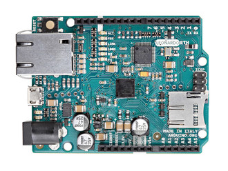
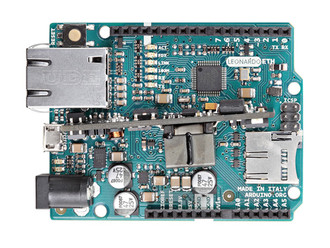
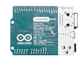
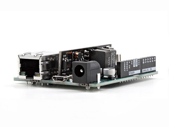
The Leonardo ETH is a microcontroller board based on the ATmega32U4 (datasheet) and the new W5500 TCP/IP Embedded Ethernet Controller (datasheet). It has 20 digital input/output pins (of which 7 can be used as PWM outputs and 12 as analog inputs), a 16 MHz crystal oscillator, a RJ45 connection, a micro USB connector, a power jack, an ICSP header, and a reset button. It contains everything needed to support the microcontroller; simply connect it to a computer with a USB cable or power it with a AC-to-DC adapter or battery to get started.
The Leonardo ETH differs from the preceding Ethernet board in that the ATmega32u4 has built-in USB communication, eliminating the need for an external USB-to-serial converter. This allows the Leonardo ETH to appear to a connected computer as a mouse and keyboard, in addition to a virtual (CDC) serial / COM port. It also has other implications for the behaviour of the board. Plus, it has the new W5500 TCP/IP Embedded Ethernet Controller onboard.
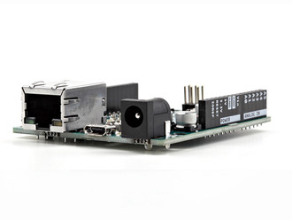
An optional Power over Ethernet module can be added to the board as well.
The Leonardo ETH has the same Wiznet Ethernet interface as the Ethernet Shield 2.
An onboard microSD card reader, which can be used to store files for serving over the network, is accessible through the SD Library. Pin 10 is reserved for the Wiznet interface, SS for the SD card is on Pin 4.
The board uses the standardized 1.0 pinout, consisting of:
added SDA and SCL pins: beside the AREF pin, two TWI pins have been added. This will allow to connect the Leonardo ETH to Shields that use the I2C or TWI bus communication for their functioning.
the IOREF: it allows the shields to adapt to the IO voltage level provided by the Board. The Shield that uses the IOREF pin will be compatible with both 3V3 and 5V (e.g Due and Uno) IO levels Arduino Boards. Next to the IOREF pin you can find another (currently not in use) pin, that is reserved for future usage.