端口 & 界面
| 数字I / O引脚的数量 |
20 |
| 脉宽调制数字I / O引脚 |
4 |
| 模拟I / O引脚的数量 |
6 |
| 支持以太网(PoE) |
Y |
| 支持以太网(PoE)电源供应 |
57 V |
内存参数
| 内存时钟速度 |
16 MHz |
| SRAM(静态随机存取存储器) |
2 KB |
| EEPROM(电子抹除式可复写只读存储器) |
1 KB |
| 闪存 |
0.032 MB |
产品特点
| 每I / O引脚的直流电流 |
40 mA |
| 格式要素 |
Arduino |
| 工作电压 |
5 V |
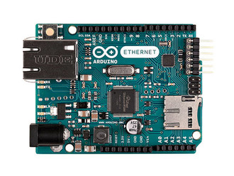
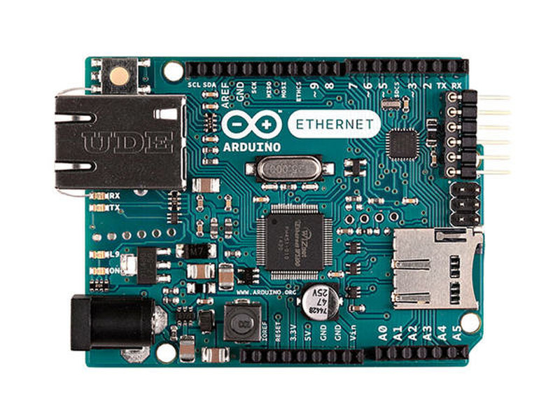
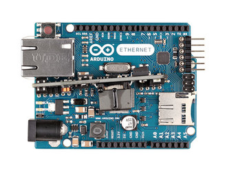
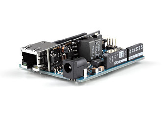
The Arduino Ethernet board is an Arduino UNO with Ethernet connectivity
The Arduino Ethernet is a microcontroller board based on the ATmega328 (datasheet). It has 14 digital input/output pins, 6 analog inputs, a 16 MHz crystal oscillator, a RJ45 connection, a power jack, an ICSP header, and a reset button.
NB: Pins 10, 11, 12 and 13 are reserved for interfacing with the Ethernet module and should not be used otherwise. This reduces the number of available pins to 9, with 4 available as PWM outputs.
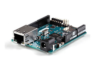
An optional Power over Ethernet module can be added to the board as well.
The Ethernet differs from other boards in that it does not have an onboard USB-to-serial driver chip, but has a Wiznet Ethernet interface. This is the same interface found on the Ethernet shield.
An onboard microSD card reader, which can be used to store files for serving over the network, is accessible through the SD Library. Pin 10 is reserved for the Wiznet interface, SS for the SD card is on Pin 4.
The 6-pin serial programming header is compatible with the USB Serial adapter and also with the FTDI USB cables or with Sparkfun and Adafruit FTDI-style basic USB-to-serial breakout boards. It features support for automatic reset, allowing sketches to be uploaded without pressing the reset button on the board. When plugged into a USB to Serial adapter, the Arduino Ethernet is powered from the adapter.
The Revision 3 of the board introduces the standardized 1.0 pinout, that consist in:
added SDA and SCL pins that are near to the AREF pin and two other new pins placed near to the RESET pin, this will the opportunity to shield that use i2c or TWI components to be compatible with all the Arduino boards;
the IOREF that allow the shields to adapt to the voltage provided from the board. Shields that use the IOREF pin will be compatible both with the board that use the AVR, which operate with 5V and with the Arduino Due that operate with 3.3V. Next to the IOREF pin there is a not connected pin, that is reserved for future purposes.