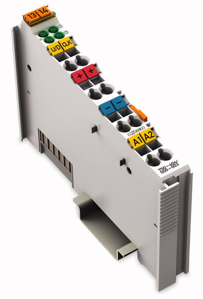

Wago 750-404/000-003 Digital output module fieldbus module
EAN: 4045454429775
MPN: 750-404/000-003
Sale and delivery by:

Where to buy and prices (Advertising *)
On Top

|
|
в наличии
|
* Alle Preise inkl. der jeweils geltenden gesetzlichen Mehrwertsteuer, ggfs. zzgl. Versandkosten. Alle Angaben ohne Gewähr. Preisänderungen sind in der Zwischenzeit möglich.
Technical specifications
On Top
-
Payment Methods
We accept: